
Design Guidelines for Custom Parts
There are many simple mistakes engineers make that can increase the cost of manufactured parts tremendously. Some of them are as simple as forgetting to change a parameter during the CAD design process. Below is a list of common issues we see with parts, and how to correct them.
Tapped Hole Depth
A common rule of thumb for threaded / tapped holes is that they should have a thread depth of at least two screw diameters in soft metals like aluminum and brass, and one screw diameter in harder materials like carbon and stainless steels. A commonly overlooked consideration, however, is maximum thread depth. After 3-4 screw diameters of thread depth, the depth-related thread strength quickly diminishes, while the manufacturing cost skyrockets.

Sharp Internal Corners
This is commonly overlooked by newer engineers who have not yet become familiar with standard manufacturing operations like turning and milling. In both operations, sharp internal corners will almost always lead impossible or expensive-to-manufacture geometry. Milling machines use cylindrical, rotating cutters. This means that it is impossible to cut a pocket with square corners. Similarly, in turned components, most inserted cutting tool have corner radii of at least .005”. Fillets should be added to turned parts, or reliefs added to provide clearance for sharp-cornered mating parts.


Length-to-Diameter (L/D) Ratios
Engineers should try to avoid designing parts which require extremely long tooling. End mills with length-to-diameter ratios of more than 5 are prone to chatter, especially in harder materials like steel. In drilling, holes with an L/D ratio greater than 8 can be troublesome, sometimes requiring special tooling or machinery. The same concept applies to long turned components. Long, thin shafts are prone to deflection and chatter, resulting in poor surface finishes and machining difficulty, or the need for specialized equipment.

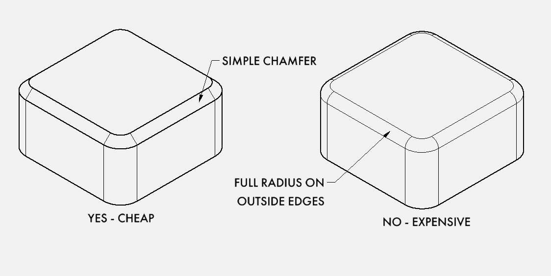
Chamfers Versus Fillets for Outside Edges
When it comes to edge breaks, chamfers are the cheaper option 99% of the time. Fillets require either radiused form cutters which can be expensive and difficult to set up properly, or the use of time-consuming 3D machining tool paths. Chamfers on the other hand, can be cut with common 45° chamfer mills. These tools can be used to cut a variety of chamfer sizes, are quick to set up, and are generally cheaper than radius cutters.
Designing Highly Manufacturable Parts
By following these simple guidelines, you can easily and significantly reduce the cost of your custom components. If you’d like to find out if your parts could use some design tweaking, try submitting them to our secure online quoting system. We’d be happy to get back to you with any relevant design suggestions.